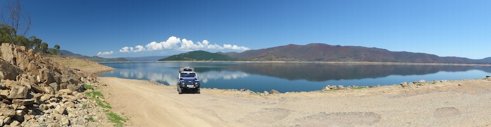
Tag Archives: Electrical

Yet more wiring !

Isolation Switches

Isolation Switches

It seems at times that the amount of wiring in the 90 just keeps going up and up and up ! This last weekend I’ve had the dash apart again, hopefully for the last time before it ships…

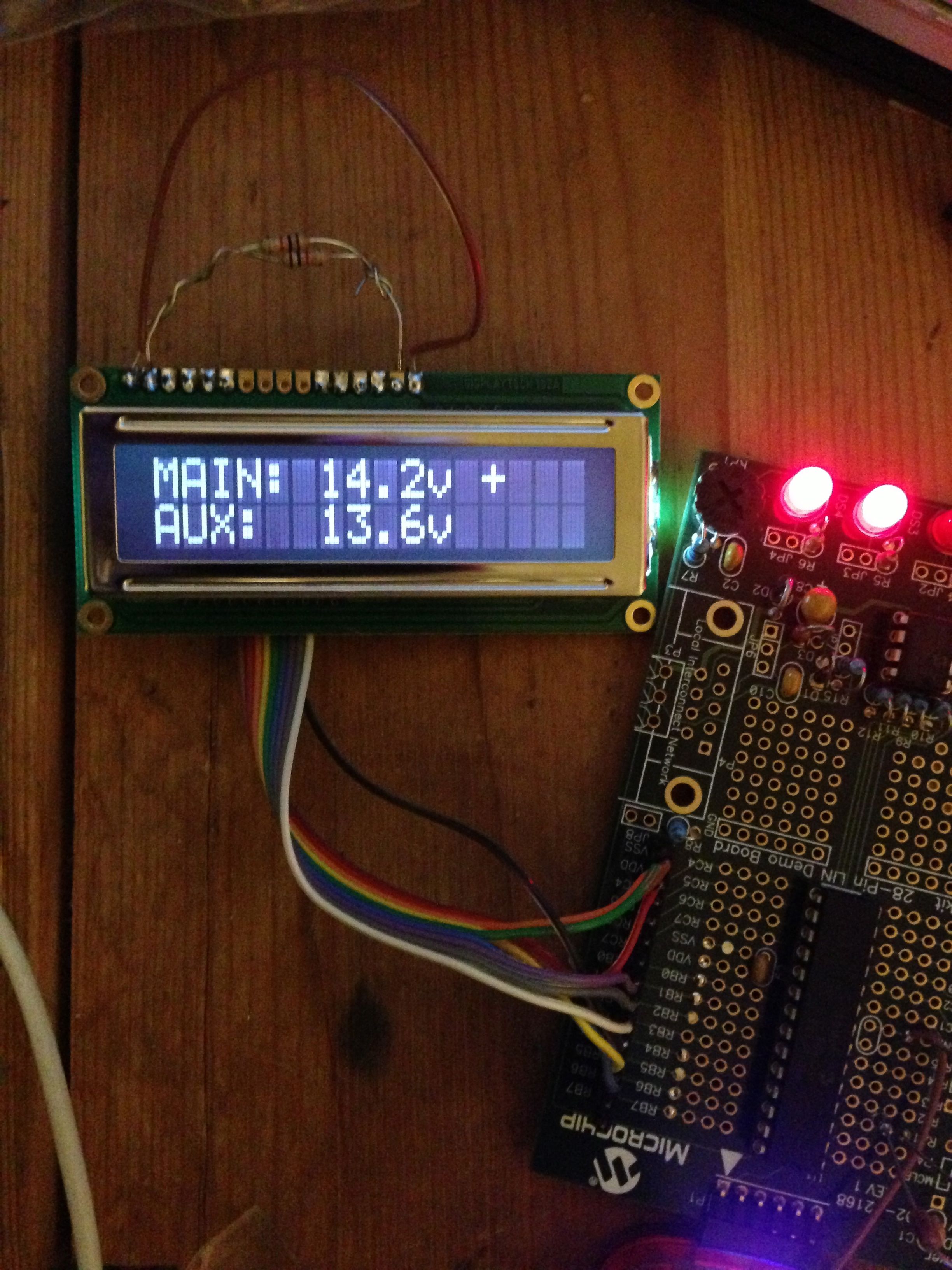
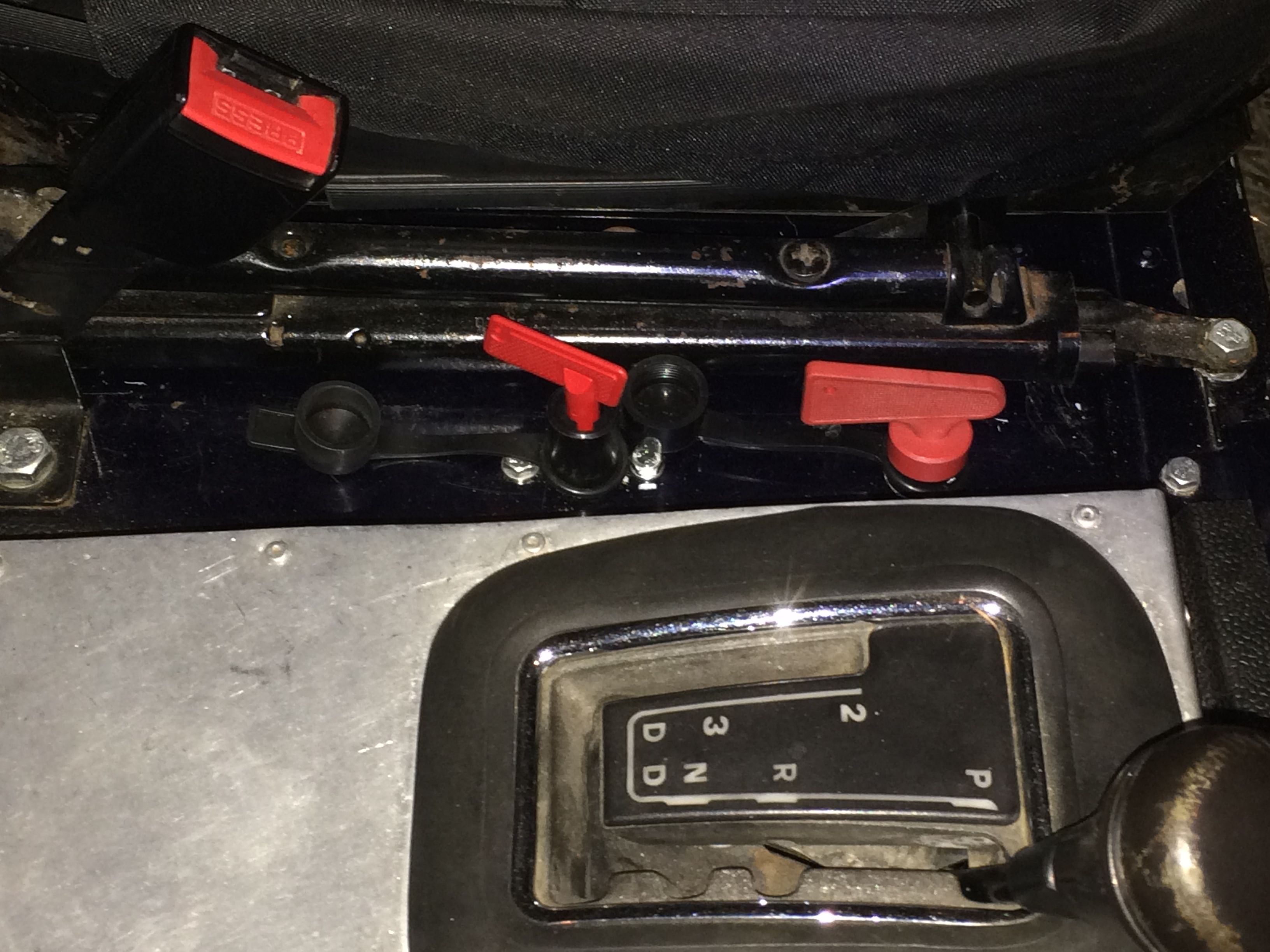
I wanted to add a couple of isolation switches both for safety and also to ensure that the batteries will make it to the other side without being discharged. I wanted to add an isolator for each battery so they could be isolated individually. If nothing else this means I can leave the auxiliary battery disconnected so if the main battery gets left on during shipping we can jump start it from the auxiliary battery. Positioning the switches so they are accessible from both seats and at the same time reduce the risk of them being accidentally switched off took some thinking about and in the end we settles for a position next to the passenger seat. The main battery switch is an FIA type which has the extra contacts that I’ve wired in so that the switch will also kill the engine if turned off with the engine running.

iPad mount and map light

iPad mount and map light

I have rewired the switches for the spotlights and the rear work lights – the rear work lights were connected to a Carling switch on the dash and the spotlights to the Land Rover spotlight switch. This was OK but didn’t give too many options for the spotlights and, as they are LEDs and can be left on for long periods without draining the battery, I wanted a switch that would allow them to be turned off, on only with main beam and on independently. To achieve this I changed them around using a Carling switch for the spots and the Land Rover dash switch for the rear working lights.

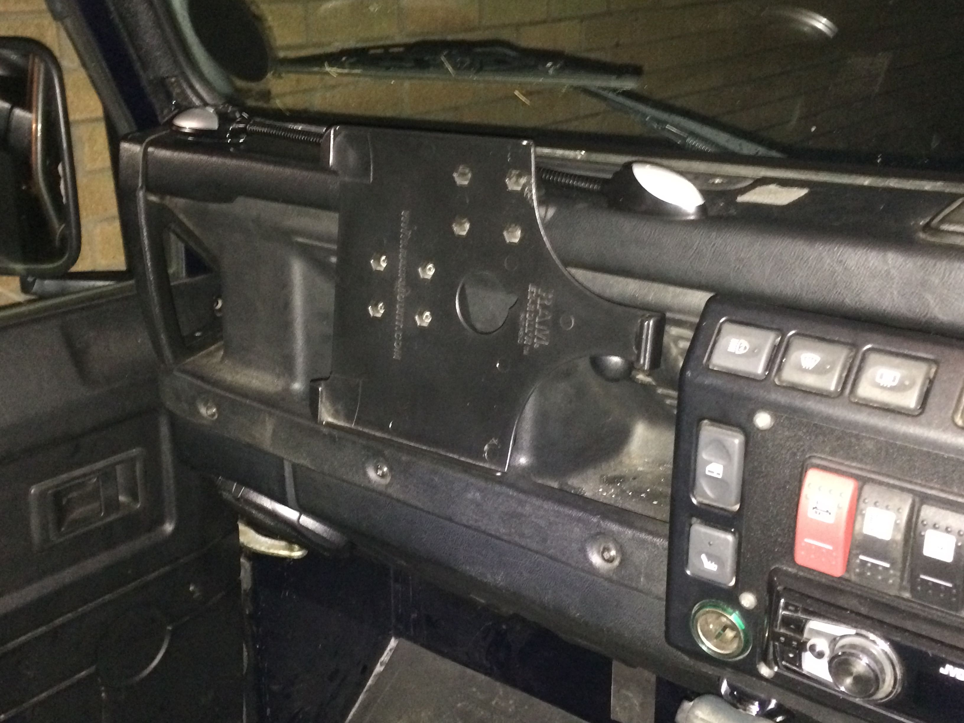
With the Dash apart I changed the iPad RAM mount from the seat mounting type to a universal mount on the dash. The seat mount is OK but tends to wobble around all over the place when you’re crossing rough ground, so much so you have to lock the rotation on the iPad. The dash mount takes up less room and will stop the annoying wobbling !

IMG_0421

Australian CB Radio

I also added an LED interior light for the passenger area that works in addition to the factory interior lights and fitted the mount for the UHF radio (Australian CB radio), connected up the power lead for the radio and the aerial lead. I also got around to fitting the map light to the top of the dash. All in all a busy few days and lots of jobs “ticked off” the list in the process 🙂


Mounted and covered !

It’s been a couple of weeks since the last update and with about 5 weeks to go before the shipping date it’s been a week of checking and re-checking what needs doing still and that we are still on track both in time and budget. Fortunately, so far, it’s looking pretty good, let’s hope it stays that way 🙂

Hi-Lift Jack in position The Hi-Lift mount is done, painted and fitted, I got some M10 ring nuts as an impulse buy while perusing an online nut and bolt shop (as you do) and it turns out they are perfect as a way of securing the Hi-Lift to the mount and providing extra tie down points. With the design I eventually came up with the Jack is secured with a single one of these nuts and is held securely with no rattling. A second nut can be added to the foot for additional security but isn’t really needed.

ECU wiring coverAnother in the long list of jobs I’ve been meaning to get around to was to make a cover for the ECU, or at least a cover for the wiring going into the ECU. Being behind the seat we’ll probably end up stuffing clothes, water, snacks and who knows what else behind the seats and there was always a danger that this would stress a wire or separate a plug so it needed to be a bit more robust.

in between rain showers and F1 coverage I ended up making 3 different covers, the first out of cardboard to use as a template, the second out of aluminium based on the template and the third because the first two didn’t quite fit right ! Third time lucky though and I’m quite pleased with the result, not too intrusive and covers all the important bits while allowing access to the fuse box and relays.

One other thing we’ve “ticked off” this week is the MOT test, the MOT is/was due to expire in March 2014 which isn’t ideal so we’ve taken it for an MOT 5 months early so it will be fully UK road legal throughout the trip (one of the requirements for use in Australia as a foreign vehicle). As expected (although always a relief !) it passed without any problems/advisories.


Fuel and battery monitor goes beta

20130621-131829.jpgThe fuel and battery monitoring system is now ready for the next stage, transferring the design from a prototyping board to a custom board design. The new 2×8 character display seems to be clear enough and is small enough to mount in the dashboard somewhere. I’ll add/maintain support for in situ programming of the PIC chip so I can tweak the calibration and display functions as required.
Hopefully I’ll get the PCB Design finished and the board etched this evening.
The module itself has suffered from a bit of bloat ware during the design process but hopefully it’s now got all the hardware features it needs to support and anything beyond that can be tweaked in the software. Once it’s all finalised I’ll create a page with the design for anyone that wants something similar.

Engine monitoring system

20130620-104113.jpg

I started to fit the sensors for the EMS today. The engine monitoring system I’ve chosen is a South African design and it should give us an early warning of any problems developing with the engine.
The EMS will monitor and display:

  • Coolant temperature
  • Coolant Level
  • Exhaust Gas Temperature
  • Oil Pressure
  • Battery voltage
  • Transfer box temperature

20130620-105003.jpgThe gauge itself replaces the standard temperature gauge and allows alarm levels to be set for any of the items it is monitoring with both a visual and audible alarm.
As I had to drain the coolant to fit the coolant temp sender I also replaced the thermostat – one of those jobs that’s been on the “to do” list for a while now.
The oil pressure sender was the only one that caused me some grief. Partly this was because the kit seemed to have the wrong adaptor with it. I had a suitable adaptor in the garage so I managed to get around that particular problem. The bracket that the sender comes with though is a bit small for it’s intended use and that, combined with limited space between the cylinder head and the air filter box made the job a real PITA.
Anyway, the sensors are in and the wiring made up to the bulkhead so just the gauge to fit and the wires to join up and it’s just about done.

Fuel and Battery Status Display

Battery monitorThe dual battery system has been missing a couple of things since I first installed it and I’ve spent a few evenings this week playing with a PIC chip and an LCD display. The aim is to have some way of checking the charge level of both batteries and to control the automatic charging of the secondary battery when the main battery is at a reasonable voltage. It will always have the manual overrides of either permanently connecting the aux battery (to jump start the main) or having it disconnected if I want to put all the charge into the main.

As the PIC chip I’ve chosen has plenty of spare capacity I also added provision for it to display the fuel level in each fuel tank too, alternating every 10 seconds between the fuel levels and the battery levels/voltage.

I’m currently using a 16×2 character display but the finished version will be 2×8 characters, allowing it to take up less dashboard space. The programming is just about done apart from calibrating the fuel levels against the two sender units, just need to build the design into something a bit smaller now !

The chip I’m using has another 4 spare analogue inputs so I might add some additional warning monitoring into it yet. Maybe gearbox temperature, fuel pressure perhaps, turbo boost pressure, I’m fitting a dedicated monitoring system so I’ll see what that’s missing and maybe add them into this chip/display. It’s always better to know when something’s starting to go wrong rather than a complete failure being the first sign of trouble.

Ready for the snow… I think…

ARB compressor and airline connectorThe last few days have been busy finishing off a number of jobs in final preparation for the trip to Scotland for the Muddy Truckers Trophy, the weather forecast hasn’t improved any… if anything it’s got worse, it’ll be a cold one that’s for certain.

Anyway, got the internal rear window guards all fitted in the back and the rear work lights wired up. The auxilliary fuse box is completely wired back in and providing power for everything it needs to, including the fridge although that may not actually be a necessity for this trip given the forecast temperatures !

Auxilliary fuse boxThe ARBs came back from Crown Diffs so I fitted the rear one together with the spare Ashcroft half shafts. I’ve had those shafts since 2008 when they formed part of the spares kit we took to Australia. They were never used so it makes sense to upgrade the 90 axles with Ashcroft shafts and CVs. The front axle will have to wait until after the Muddy Truckers though as we’re missing a couple of bits.

I plumbed in the ARB compressor, running the pipework for both front and rear diffs, the winch free spool and an airline connector on each side of the vehicle for blowing up tyres etc…

Window guards

Other than packing some tools and the rest of our camping gear, clotting, food, water etc… we’re about ready to go. The pile of bits in the dining room is definitely diminishing 🙂

Back on the roof !

Roof tent mountingWe re-fitted the roof tent today after it’s winter break. It’s actually barely above freezing during the day at the moment but we’ll be camping in it at the Muddy Truckers Trophy so the sooner it’s back on, the better. There’s snow forecast in the run up to the event, fingers crossed that changes !

As with getting the tent off the roof in the first place I decided to use the strap and winch ramp technique. With a long strap from the roll cage to the end of the bumper on my challenge motor and a second strap from the cage to the winch (allowing that strap length to be “adjusted”) we placed the roof tent on the trusty Black and Decker work bench then drove the challenge motor backwards. As the straps tightened the roof tent was lifted off the work bench and then it’s just a case of pushing the tent up the ramp… carefully !

Roof tent mounting 2For once refitting was the reverse of removal and all went smoothly. We mounted the tent a lot further forward this time to see how it would work, time will tell.

With the roof tent on I fitted and wired up a couple of LED rear work lights as we’re almost certain to be needing them in Scotland and no doubt will end up setting up in the dark on at least one night.

Roll cage finished at last :)

Spent a bit of time tinkering with the electrics, tidying up a few bits and pieces and starting to map out the circuit diagram for the aux fuse box. The aux fuse box has sort of evolved over time as each new circuit was added and I ended up with no real idea which fuse was now used for what. I now have a full circuit diagram that will sit in the top of the fuse box for reference and also allow me to wire it back up again correctly !

The side windows on the 90 have rattled pretty much since we got it and have never actually sealed properly from what I can remember. We also want to fit internal window guards at some point and all the available ones we like are designed to fit standard Land Rover pattern windows, which the ones fitted aren’t. The upshot of this is that we’ve bought a pair of new windows from Masai which are pretty much OEM spec and “guaranteed” not to rattle so we can get rid of the bits of card/cloth/paper that have been pushed into the joints in an attempt to stop it rattling.

The first problem with changing the windows is the fact that the roll cage is in the way so replacing the windows first involves removing the whole of the rear half of the roll cage. When we fitted the cage we left four bolts out (two on each side) because to drill the holes meant marking them then taking the rear of the cage off again. So, as well as replacing the windows now was the time to finally finish off the cage installation !

It took pretty much the whole day to do the job as, as it turns out, not only did the old windows not use OEM catches they were also a different shape ! This meant quite a lot of time was spent cutting and filing the existing opening out to make it big enough for the new windows. Eventually though the windows were in and the roll cage refitted complete with the new bolts to connect the top of the sides with the internal hoop. While the rear cage was off I also made some gaskets to go between the cage mounting plates and the body, cut from a large sheet of butyl rubber that used to line our pond.

First tests show that the windows don’t rattle and they seem to be water tight… so that’s a bonus !

Clearing the under seat box

Plan A - ECU and fuse box position behind driver's seat.

Plan A – ECU and fuse box position behind driver’s seat. A nice idea but no way the looms will reach.

Having quite a few days holiday left to book before April and intending to head up to the Muddy Truckers Trophy at the end of the month, I’ve booked quite a few days off this month with the intention of spending a lot of them working on the 90.

The first job on the list was to clear the underseat box where the engineECU, gearbox ECU and fuse box are located. There are a LOT of wires under there with the 2 big vehicle wiring looms and the gearbox loom.

The initial plan was to try and move everything behind the driver’s seat, if necessary extending the looms although, if possible, I wanted to avoid that. After disconnecting all the wiring and tracing it’s route it became increasingly clear that moving everything behind the driver’s seat would be a much bigger job than moving everything behind the passengers seat. The trouble was that I’d also mounted the aux fuse box and ARB compressor behind the passenger’s seat.

So, the plan got a lot more complicated as I ended up having to move the aux fuse box and ARB compressor to the driver’s side to make room for the engine ECU etc… The good news was that the route of the main and engine looms meant that both looms would be long enough to reach without modification/extending although a few wires would have to be extended such as the diff lock and high low switch wires but that’s no problem.

Plan B - Main two looms relocated behind passenger seat

Plan B – Main two looms relocated behind passenger seat – gearbox ECU on top of wheel arch.

Having checked the lengths of the looms and made sure I got them the correct way round, the first step was to drill the holes for the two looms to come through the floor having removed the aux fuse box and the ARB compressor. On mine this was limited by the length of the bulkhead loom so that was the important one to get right. Once that was in the engine loom hole went in alongside it.

I took the opportunity to tidy up the gearbox ECU wiring too, shortening the loom to length. When it had been mounted under the seat it didn’t really matter too much how much wire was floating about so I just used the whole loom as supplied with the ECU.

ECUs, relays and fuse box relocated.

ECUs, relays and fuse box relocated.

I made up a mounting bracket for the fuse box and cut up an old bulkhead fuse box plate to make a mounting plate for all the relays to mount onto on the front of the wheel arch. The final task was to make a mounting plate for the engine ECU to mount to. The intention is to make a cover that goes over the whole setup but that will probably have to wait for a while as it’s not a priority.

The good news is that, after this major surgery, the engine and gearbox and all connected circuits are working fine again so I can move onto the next job. Just need to get the aux fuse box, ARB compressor and subwoofer back in now and put the interior back together again !

Starting to move the wiring

One of the windscreen wiper gear boxes failed on the 90 a couple of weeks ago. Unfortunately it was the driver’s side one which is the more difficult of the two to replace. It’s a full dashboard out job so I thought, as I was going to have the dash apart I’d start moving some of the electronics from under the driver’s seat at the same time.

Anyway the wipers are working fine again now and should be good for another 15 years and the under seat ECU box is now a little less crowded than it was and I’ve rerouted some of the dashboard power from the aux fuse box.